Self-Tuning Algorithm For DSP-Based Motion Control
 This project involves the development of an adaptive control algorithm for Computerized
Numerical Control machines implemented in a multi-axis motion control board based on a
floating-point DSP chip.
This project involves the development of an adaptive control algorithm for Computerized
Numerical Control machines implemented in a multi-axis motion control board based on a
floating-point DSP chip.
The self-tuning control process involves adaptive modeling of the plant and application
of an inverse controller to enhance the step response of the system.
When the resulting self-tuned inverse controller is applied, the step response of the
overall system is improved in terms of shortened rise time while simultaneously avoiding
the occurrence of overshoot.
The performance of this solution was verified at three different levels: Software
simulation, implementation in a set of isolated motor-encoder pairs and implementation in
a real machine. The use of the adaptive inverse controller effectively improved the step
response of the system in all three levels. In the simulation, an ideal response was
obtained. In the motor-encoder test, the rise time was reduced by as much as 80%, without
overshoot, in some cases. Even with the larger mass of the actual machine, decrease of the
rise time and elimination of the overshoot were obtained in most cases.
Results obtained through Software Simulation
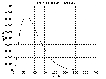
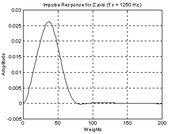
The following figure represents the plant model obtained using a
theoretical plant representation for a typical machine axis:
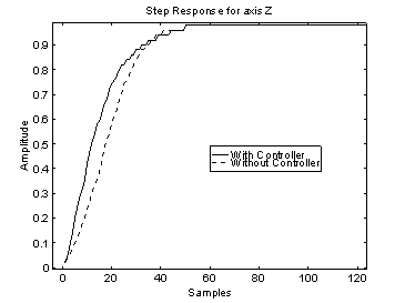
The plant model was used to build an inverse controller that eliminate the effect the
plant has over the input signal. The following figures display the step response
with and without the inverse controller:
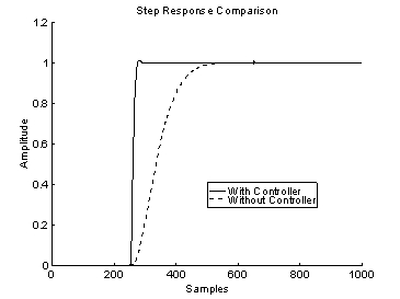
It is clearly observed that the performance of the system is enhanced by application of
the inverse approach. The rise time of the system is considerably improved without
the inconvenience of large overshoot.
Real-Time results Obtained With a Motor-Encoder Set (No-load Case)
An isolated motor-encoder set was used to test the performance of the algorithm in a
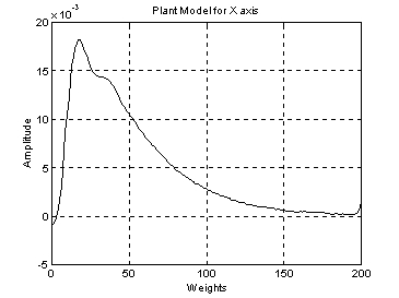
real-time environment. The following figure depicts the model obtained by the
combination of the DAC, amplifier, motor and encoder, in a negative feedback loop
configuration:
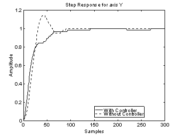
The real-time performance of the adaptive algorithm is shown in the following figure:
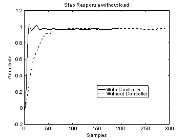
The rise time of the system using the inverse controller was decreased from 74 samples
(without) to only 10 samples.
Real-Time Results Obtained with a Machine
The following figure represents the model obtained from one axis of an actual machine:
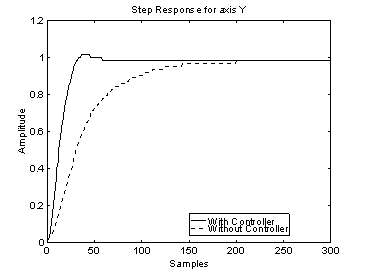
The performance of the inverse controller in this system is illustrated in the
following figure:
Improvement in the step response can be seen after using the inverse controller.
Similar real-time implementations and verifications of the approach demonstrated
that it is capable of significantly correcting deficient responses, like the ones shown
below :
|